
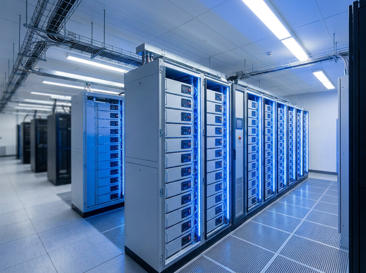
This article follows on from our previous piece, Data Centres Power the Digital Economy — So Why Are We Still Throwing Their Energy Away?, which explored how data centres should be understood as participants in the wider energy system, covering power usage effectiveness, cooling, heat recovery, renewable generation, battery storage and grid flexibility. One idea from that discussion deserves more detailed examination: whether the battery capacity that data centres already own for resilience could, under the right conditions, do considerably more useful work.
Data centres already own batteries
Most modern data centres rely on some form of UPS energy storage or equivalent short-duration resilience system. This is not optional infrastructure. Uninterruptible power supply (UPS) batteries are the first line of defence between a grid failure and the loss of critical IT load. They provide ride-through time while generators start, handle short-duration supply disturbances, and protect sensitive equipment from power-quality events.
A large data centre might hold tens of megawatt-hours of UPS battery capacity across its infrastructure. A hyperscale facility could hold considerably more. This is a substantial capital asset — and in the majority of installations, its operating role is to sit charged and wait.
At the same time, many of the same data centres are now evaluating or installing separate battery energy storage systems (BESS) for an entirely different set of purposes: peak shaving, demand management, electricity-price optimisation, frequency response, and grid services participation. These two battery systems — one for resilience, one for energy management — are typically designed, procured, installed, and operated as completely independent infrastructure.
The question worth asking is straightforward: why?
What a traditional UPS battery actually does
To understand the opportunity, it helps to be precise about what conventional UPS batteries are actually asked to do.
In a standard data centre architecture, the power flow runs from the grid through medium-voltage switchgear, transformers, and then through the UPS to the critical IT load. The UPS battery provides backup power in two situations: first, during a momentary or sustained grid failure, supplying power to the critical load while the diesel generators start and stabilise; second, during minor power-quality events — voltage dips, transients, brief supply interruptions — where the battery absorbs the disturbance without the generators being involved at all.
The required autonomy period — the time the battery must support the full critical load on its own — varies by site design and redundancy tier, but a common target is between five and twenty minutes. This is enough time for generators to reach stable operating temperature and for transfer to take place in a controlled sequence.
The result is a battery system that experiences very few discharge cycles over its operational life. Most UPS batteries in traditional installations cycle infrequently, often less than once per year under genuine emergency conditions. The battery is maintained at a high state of charge, routinely tested, and otherwise held in readiness. It is, in engineering terms, an insurance policy — essential, expensive, and largely idle.
Why separate UPS and BESS systems can create duplication
When an organisation then decides to install a BESS for energy management purposes, it typically designs and procures a completely separate system. This creates potential duplication across a significant range of infrastructure:
- –Battery cells and modules
- –Power conversion equipment (inverters, bidirectional converters)
- –Switchgear and protection systems
- –Cabling and containment
- –Control and monitoring systems
- –Cooling and thermal management
- –Fire detection and suppression
- –Physical housing (battery rooms, containers)
- –Maintenance contracts and inspection regimes
The degree of genuine duplication depends heavily on the site architecture, the UPS topology, the required redundancy level, the battery chemistry in use, and the operational requirements of both systems. Not every component can be consolidated in every design, and some separation may be required by the system architecture or by regulatory and standards requirements. The point is not that integration is always possible or always straightforward — it is that the question of whether it is possible is not being asked consistently enough.
A BESS installed for peak shaving already needs to be connected to the main electrical infrastructure, sized appropriately, monitored continuously, thermally managed, and protected against fault conditions. A UPS battery system already requires all of the same things. Where these requirements overlap, the case for examining whether a single integrated system could serve both roles deserves serious consideration.
What is a grid-interactive UPS?
A grid-interactive UPS is, in broad terms, a system in which the UPS battery can participate in energy management and grid service functions during normal operating conditions — not only in emergency backup mode.
Modern lithium-ion UPS systems, combined with suitable bidirectional power conversion electronics, can potentially allow the battery to perform functions beyond emergency backup. These include:
Peak shaving — reducing maximum grid import by discharging the battery during periods of high demand, then recharging during lower-demand periods.
Time-of-use optimisation — charging the battery when electricity is cheaper or lower carbon, discharging it when electricity is more expensive or more carbon-intensive.
Demand response — responding to signals from the grid operator or demand flexibility aggregator to adjust consumption at defined times.
Frequency response — providing fast-acting power injection or absorption to help stabilise grid frequency, as part of a contracted grid service.
Renewable energy integration — absorbing surplus generation from on-site solar PV or a renewable PPA, storing it, and releasing it to serve IT load when renewable output is low.
Network constraint support — providing localised support during periods when the local distribution network is under stress, potentially deferring or avoiding reinforcement costs.
This is not a theoretical proposition. Eaton, Schneider Electric, Vertiv, and ABB have all developed or commercialised UPS architectures designed with grid-interactive capability in mind. Microsoft has published material on its research into using data centre battery infrastructure for grid services. National Grid ESO and its European counterparts have accepted battery storage systems — including those associated with critical infrastructure — as participants in frequency response and demand flexibility markets, provided the systems meet the required technical specifications and response characteristics.
The concept is established. The question for any given data centre is whether the conditions for safe and effective implementation exist.
Worked example: a 10 MW data centre
Consider a data centre with a critical IT load of 10 MW and a UPS autonomy requirement of 15 minutes.
The theoretical minimum energy required to support that load for 15 minutes is:
This is the theoretical floor only. Any real design adds substantial engineering margins to account for inverter and conversion losses, battery ageing over the system lifetime, a minimum state of charge below which the battery should not be discharged, temperature effects on available capacity, redundancy requirements (N+1 or 2N battery string arrangements are common), and a reserve against individual string or module failures. In practice, a 10 MW data centre designed to a 15-minute autonomy requirement with appropriate engineering margins and redundancy could easily require installed battery capacity of 7 MWh, 10 MWh, or more.
Now consider a system with 10 MWh of total installed battery capacity. Of that, a portion — determined by engineering analysis, not commercial optimism — is ring-fenced as an untouchable emergency reserve. This protected reserve must always be available to support the full critical IT load for the required autonomy period under worst-case conditions. It cannot be intentionally discharged for any commercial purpose.
The remainder of the capacity, above that protected reserve, could in principle be available for controlled energy management activities during normal grid-connected operation. If the battery is at 90% state of charge and the protected resilience reserve requires 40% state of charge, there is a band of capacity between those two levels that is not serving any immediate resilience function.
Whether that band can be used commercially is an engineering and operational question, not a financial one. The financial analysis comes later.
Protecting the resilience reserve
The control philosophy for any grid-interactive UPS must follow a strict priority hierarchy:
- 1.Protect the critical IT load at all times
- 2.Maintain the required UPS autonomy at all times
- 3.Maintain redundancy requirements at all times
- 4.Only then use remaining capacity for commercial or grid service functions
This hierarchy is not negotiable. Every line of energy management software, every dispatch instruction from an aggregator, every demand response signal must be processed through a control layer that checks battery state against the resilience reserve before executing any commercial activity.
The minimum state of charge concept is central to this. Suppose engineering analysis determines that 40% state of charge is the absolute minimum required to guarantee the full autonomy period under worst-case conditions — accounting for losses, degradation, temperature, and redundancy. The energy management system must never intentionally discharge the battery below that threshold for any commercial reason.
The actual reserve level is a site-specific engineering decision and cannot be generalised. It depends on the battery chemistry, the age and condition of the battery, the redundancy architecture, the IT load profile, the generator start-up time, and a range of other factors. It should be recalculated periodically as the battery ages and its available capacity changes.
What happens when the grid fails?
Under normal conditions, the battery may be participating in a peak shaving or demand response event. The moment a supply failure is detected, commercial dispatch ends. The UPS reverts immediately to backup mode. If the battery is above the resilience reserve threshold — as it must always be — the critical IT load is supported without interruption. Generators start on their normal sequence. Once a stable alternative supply is available, the UPS transitions according to its designed architecture.
Commercial use of the battery capacity must never prevent the facility from meeting its defined resilience requirement at the instant of an outage. This is the non-negotiable condition on which the entire concept rests.
Peak shaving and tariff optimisation
For a 10 MW data centre, the electricity costs associated with peak demand charges can be substantial. Half-hourly settlement under flexible tariffs means that the cost per MWh can vary significantly across the day, week, and season. A data centre paying a demand charge based on its maximum import in a settlement period has a clear incentive to reduce that maximum, even briefly.
A battery system that can discharge during a high-tariff period and recharge during a low-tariff period provides real economic value. If that battery system is also the UPS battery — or shares significant infrastructure with it — the economics become more attractive because the capital cost of the battery is already justified by the resilience function.
The energy management system needs to know: when is electricity most expensive, when is demand highest, and how much battery capacity is available above the resilience reserve? With that information, an intelligent dispatch algorithm can reduce peak import, optimise tariff exposure, and potentially reduce the site's maximum demand charge over a billing period.
Data centre battery storage systems engaged in peak shaving are not a new development. What is less common is the explicit integration of this function with UPS architecture and the clear engineering delineation of which capacity is protected and which is available for dispatch.
Grid services
Beyond the site boundary, data centre battery energy storage in the UK can participate in grid service markets. National Grid ESO operates a range of ancillary service products, including dynamic frequency response, static frequency response, and various demand flexibility and balancing mechanism products. The Capacity Market also provides income streams for assets that commit to being available during periods of high system stress.
A grid-interactive UPS or associated BESS that meets the required response times, ramp rates, and communication standards could potentially participate in these markets — either directly or through an aggregator that combines capacity from multiple sites.
The qualifying conditions matter. Frequency response services require fast-acting assets that can respond to frequency deviations within seconds. A UPS battery integrated with suitable power electronics is technically capable of this. The system must also be able to guarantee availability and meet the dispatch conditions of the contracted service. For a data centre, the critical question is always whether contractual grid service obligations are compatible with the priority hierarchy described above — and whether the system can reliably demonstrate that the resilience reserve is maintained at all times.
Grid service income from a single data centre battery is unlikely to transform the site's operating economics. But combined with peak shaving, tariff optimisation, and avoided capital cost through reduced duplication, it contributes to a more compelling whole-system economic case.
Renewable energy integration
The previous article in this series discussed the role of data centres in the wider energy system, including the potential for on-site renewable generation and renewable power purchase agreements. A grid-interactive battery system is a natural complement to renewable integration.
A data centre with on-site solar PV — or access to a renewable PPA with variable output — faces a challenge that storage can address. When renewable generation exceeds IT load, surplus energy either exports to the grid (if the connection permits) or is wasted. A battery can absorb that surplus, store it, and release it to the IT load when renewable output falls. This increases on-site renewable utilisation, reduces grid import, and may improve the site's carbon intensity profile.
The integrated architecture a future data centre might operate towards could look something like this:
In this architecture, the battery is not a passive backup device or a separate energy management tool. It is the electrical balancing layer that allows the whole system to operate coherently — absorbing renewable variability, managing grid demand, providing resilience, and enabling the other energy outputs of the data centre to be maximised.
Interaction with backup generators
The relationship between UPS batteries and diesel generators is worth addressing directly. Data centres have traditionally relied on generators for long-duration resilience — the battery buys time while the generator starts; the generator then supplies power for as long as fuel is available.
Could a larger, grid-interactive battery system reduce dependence on diesel generators? Possibly, in limited respects, and with considerable caution.
A larger battery system can extend the ride-through time available without generators. It can handle short outages — lasting minutes rather than hours — without needing generators to start at all, reducing generator run hours and associated maintenance. It can allow generators to be started more slowly and more carefully, reducing mechanical stress and fuel consumption. In some architectures, a combination of large battery capacity and on-site renewable generation could handle a greater proportion of outage scenarios without diesel.
But very long-duration resilience is a fundamentally different problem from short-duration battery backup. A data centre that needs to operate for hours or days during an extended grid failure needs either a very large battery (with all the cost, space, and weight implications that implies) or an alternative generation source. Lithium-ion batteries are well-suited to the short-duration, high-power applications that grid services and peak shaving require. They are less suited, economically and practically, to multi-hour emergency generation. Diesel generators remain the most practical technology for that application at present.
Battery systems can reduce generator use, reduce generator starting frequency, and handle a wider range of short outages without generation — but they are not a universal replacement for generators in data centre applications.
Battery degradation and lifecycle economics
UPS batteries in traditional installations experience very few cycles. The battery is held at high state of charge, tested occasionally, and discharged under genuine emergency conditions rarely — perhaps never, in a well-maintained facility over a five-to-ten-year battery life.
Commercial use introduces additional cycling. Peak shaving and grid services involve daily or near-daily charge and discharge cycles. This accelerates degradation in proportion to the depth of discharge, the number of cycles, the operating temperature, and the battery chemistry.
Lithium-ion battery chemistries used in modern UPS systems — most commonly lithium iron phosphate (LFP) or lithium nickel manganese cobalt oxide (NMC) — are substantially more cycle-tolerant than the valve-regulated lead acid (VRLA) batteries traditionally used in UPS applications. A well-managed LFP system might support thousands of cycles to significant depths of discharge before reaching end of life. A VRLA system in the same application would degrade far more rapidly.
This is a central reason why the grid-interactive UPS concept is more practical with modern lithium-ion systems than it was with the previous generation of UPS battery technology. The higher cycle life, better state of charge visibility through the battery management system (BMS), higher energy density, and faster charge-discharge capability all support the case for dual-purpose operation. That said, not all lithium-ion UPS systems are automatically suitable for grid-interactive operation — architecture, warranty terms, and protection requirements all need to be evaluated.
The correct engineering question is not whether the battery can be cycled commercially. It is: does the economic and operational value created by cycling exceed the cost of additional degradation while preserving the required reliability?
This requires a lifecycle model that accounts for the degradation curve specific to the chemistry and depth of discharge; the replacement cost of cells or modules as capacity falls below the required threshold; the maintenance and monitoring costs associated with a more actively used system; and the revenue or cost savings generated by the commercial activities. If the numbers work — and for well-designed lithium-ion systems operated within appropriate depth of discharge limits, they often do — then the additional cycling is a justified operating cost.
Battery warranties from manufacturers typically specify maximum cycle counts or degradation limits. Any grid-interactive UPS strategy needs to be checked against the relevant warranty conditions, and any additional degradation beyond the warranty baseline needs to be factored into the economic model.
Electrical and grid-connection considerations
From an electrical engineering perspective, implementing a grid-interactive UPS or combined UPS/BESS system introduces a range of considerations beyond the UPS architecture itself.
The grid connection must be able to handle import and export flows if the battery is to participate in grid services or renewable export. This means reviewing the existing connection agreement, import and export limits, and whether the current metering and protection arrangements support bidirectional flow.
In the UK, connections above a defined capacity threshold fall under Engineering Recommendation G99 or G100, both of which apply in the distribution network context. G99 covers the connection of generating plant and storage to distribution networks, while G100 deals specifically with export limitation schemes. These set technical requirements for protection, anti-islanding, power factor, harmonic performance, and fault-level contributions. Any battery system intended to export to the grid must comply with the relevant standard and obtain the necessary connection approval. These requirements and their thresholds are subject to periodic revision, and current requirements should be confirmed with the relevant network operator before design is finalised.
The power conversion equipment — the inverters and bidirectional converters that interface the DC battery to the AC electrical system — must be capable of the response times and output quality required for the intended grid services. Not all UPS inverter topologies are suitable for grid-interactive operation without modification or replacement. The harmonics, power factor, and voltage regulation behaviour of the converter under grid service dispatch conditions need to be evaluated and confirmed against network requirements.
Fire detection and suppression for lithium-ion battery installations are governed by their own requirements, which differ from those applicable to VRLA UPS batteries. Thermal management is critical — both for battery performance and for safety. A system that is being cycled commercially will generate more heat than a standby UPS battery, and the thermal management design must account for this.
EMS and SCADA integration is needed to coordinate the UPS control system, the energy management software, the grid service dispatch interface, and the wider building management or site monitoring system. The control hierarchy described earlier — resilience first, commercial use only from surplus capacity — must be implemented and validated in this integrated control architecture, not assumed.
What future data centre architecture could look like
The traditional model — UPS battery for resilience, separate BESS for energy management, diesel generators for extended backup — reflects how these technologies were developed and deployed independently of one another. Each piece of infrastructure was designed to perform one job.
A more integrated approach starts from a different question: what electrical energy storage does this facility actually need, and how can that storage be designed to serve all the required functions safely and efficiently?
The answer might be a single battery system, designed from the outset for dual-purpose operation, with a clearly defined and technically enforced resilience reserve, sophisticated energy management software, and appropriate grid connection and protection arrangements. It might be a hybrid architecture in which the UPS battery system and a separate BESS share common power conversion infrastructure or control systems while retaining some electrical separation. The right answer will depend on the facility's redundancy requirements, the scale of the battery, the available grid connection, and the maturity of the energy management technology.
What is clear is that installing infrastructure that performs only one job — when that same infrastructure could safely perform several — represents a form of inefficiency that is increasingly difficult to justify. A battery required for resilience is already connected to the electrical infrastructure, already monitored continuously, already maintained, already housed in a controlled environment. If part of that installed capacity can provide useful energy services without compromising its primary role, then leaving that capability unused has a cost — both economic and in terms of the broader case for intelligent energy management.
Larger organisations building or operating data centres at significant scale are already beginning to design around this principle. The technology, the grid service markets, and the regulatory frameworks are sufficiently mature that the engineering question is no longer whether it is possible. It is whether the design, control architecture, and economics have been worked through carefully enough to do it safely and profitably.
Conclusion
Data centre UPS batteries represent a substantial and largely underutilised asset. The case for grid-interactive UPS systems — or for more deliberately integrated battery architectures that serve both resilience and energy management functions — is supported by the available technology, the established grid service markets, and the economics of reducing capital duplication.
But the case rests entirely on one condition being met without compromise:
A data centre must never trade resilience for energy-market revenue.
Any grid-interactive UPS strategy must demonstrate that:
- –Required UPS autonomy remains available at all times, accounting for battery ageing and degradation
- –Redundancy requirements remain intact under the energy management control strategy
- –Battery condition is continuously monitored, with individual string and module failures accounted for
- –The worst-case grid failure scenario — maximum IT load, lowest expected battery capacity — can still be supported within the required autonomy period
- –Additional battery cycling from commercial use is explicitly included in the lifecycle model and does not compromise reliability below acceptable thresholds
The right framing is not monetising UPS batteries. It is designing electrical infrastructure that performs all of its required functions coherently — resilience, energy management, and grid participation — from a single, well-engineered system with a clearly understood priority hierarchy. That requires engineering rigour, not financial optimism.
The data centre industry is moving in this direction. The question for any individual operator is whether their current or planned infrastructure has been designed to enable it, or whether the opportunity is being left on the table by default.
Thinking about battery storage, commercial electrical infrastructure or energy management?
As electrical infrastructure, battery storage and energy management become increasingly interconnected, commercial energy systems need to be designed as a whole rather than as isolated components. Omni3 works across commercial electrical infrastructure, solar PV, battery storage and energy management, helping businesses understand how these technologies can operate together. Talk to our team about your project.
Sources and further reading
- Eaton Corporation — 9PX and 93PM UPS product documentation (grid-interactive capability)
- Schneider Electric — EcoStruxure and Galaxy series UPS technical literature
- Vertiv — Liebert EXL S1 and GXT series UPS technical documentation
- Microsoft Research — data centre battery grid services research
- National Grid ESO — Balancing Services (frequency response, demand flexibility)
- Energy Networks Association — Engineering Recommendation G99 and G100
- Uptime Institute — Global Data Center Survey (UPS and resilience benchmarks)
- ASHRAE — Thermal Guidelines for Data Processing Environments
Published September 2026 · Omni3 Limited, Pulborough, West Sussex. Engineering Recommendation references reflect UK requirements at time of publication; confirm current G99/G100 thresholds and connection requirements with your network operator. Grid service product names and specifications are subject to change. No financial returns are guaranteed without a site-specific analysis.