
When an Immersion Heater Fault Reveals a Much Bigger Electrical Problem
A call to investigate a failed immersion heater switch uncovered an overloaded circuit, heat-damaged accessories and a connection that had been deteriorating under load — without tripping a single circuit breaker.
26 A
Estimated load on a 16 A circuit
2 × 3 kW
Immersion heaters on one circuit
0
Circuit breaker trips — fault developed silently
Thermal imaging
Post-repair verification
“The immersion heater won’t switch back on”
The initial call sounded straightforward. The customer explained that his immersion heater had stopped working. He had attempted to switch it off and back on again, but the switch would no longer operate correctly.
There was useful context behind the problem. The customer had historically heated his home and hot water using heavy oil. With the cost of oil having risen considerably and energy prices becoming increasingly unpredictable, the electric immersion heaters were being relied upon much more heavily for hot water. That change in how the installation was being used ultimately exposed a problem that may have existed for some time.
There were two immersion heaters, each controlled by a fused connection unit. Externally, both units looked reasonably normal. There was no immediately obvious sign of the extent of the problem.
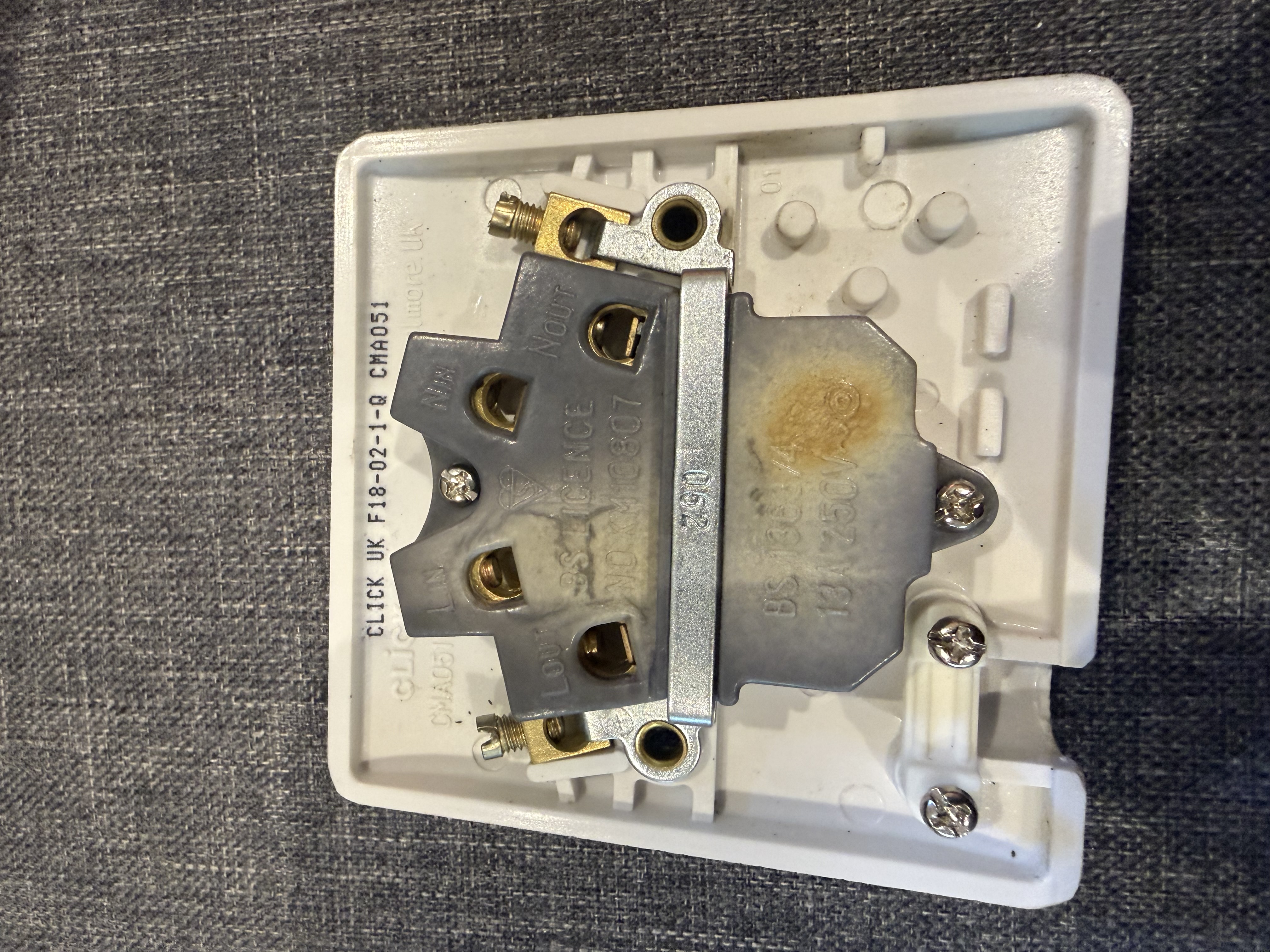
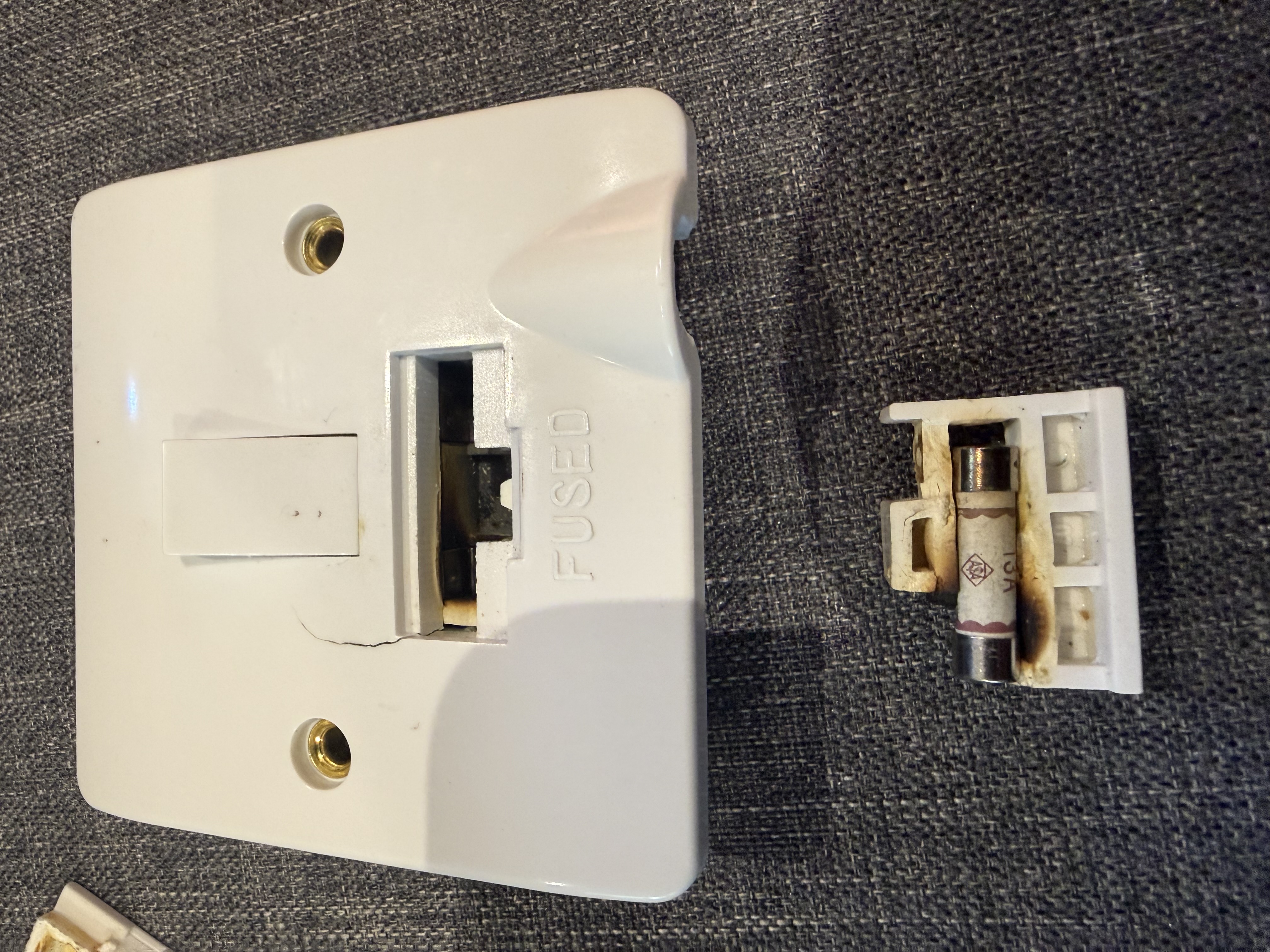
However, when we attempted to remove the fuse carrier from one of the units, it had effectively become fused into the accessory due to heat damage. The switch mechanism had also failed in the off position.
That immediately suggested this was more than simply a failed immersion heater.
Finding the circuit
The next step was to safely isolate the immersion heater circuits at the consumer unit. We expected to find two circuits — one supplying each 3 kW immersion heater.
Instead, we found only one 16 A circuit.
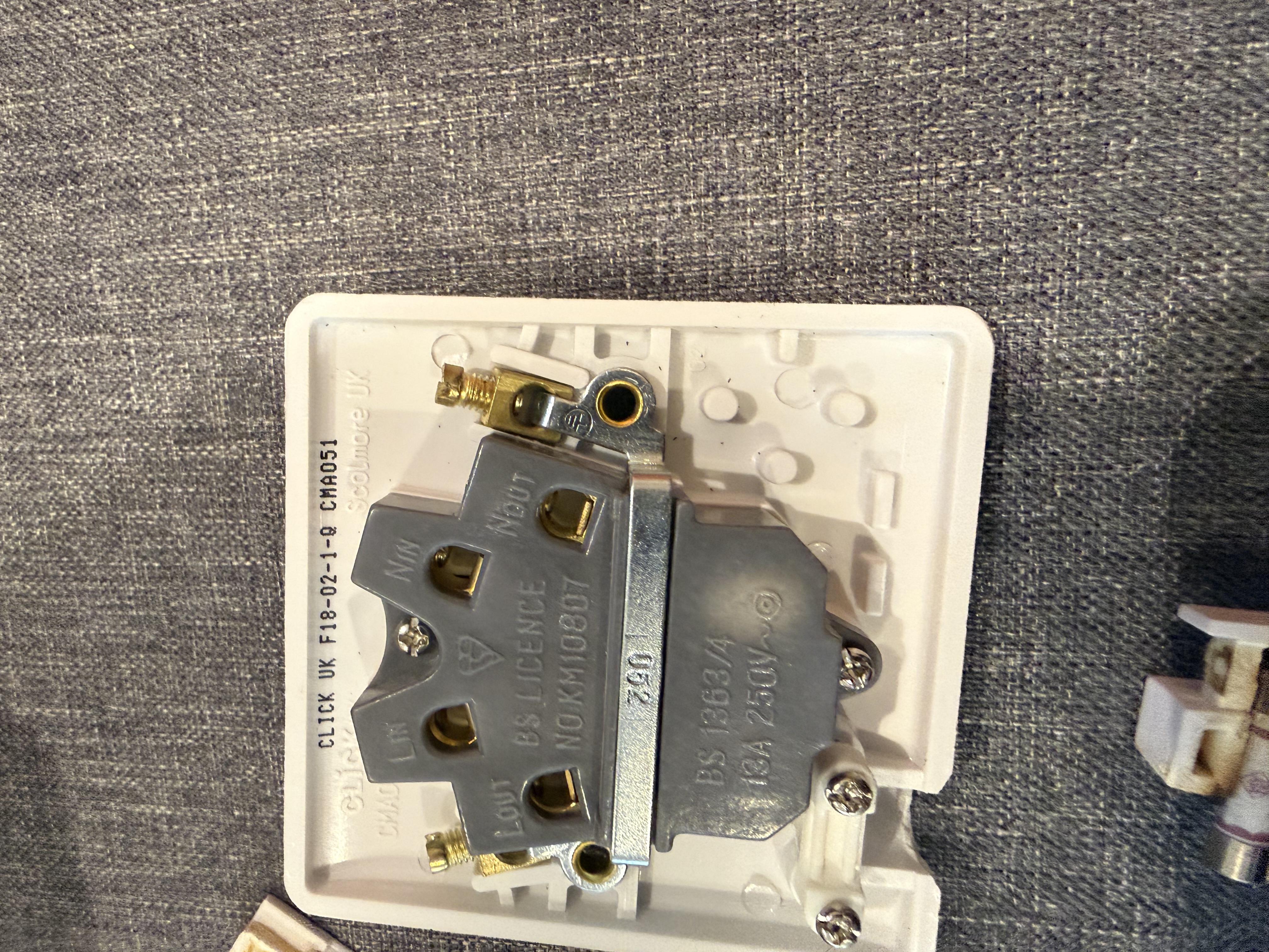
After isolating that circuit and proving dead at the fused connection unit, we removed the accessory to inspect the wiring. The reason for the overheating quickly became apparent. One 16 A circuit was supplying both 3 kW immersion heaters. There was also visible heat damage, including blackening to one of the supply conductors.
The numbers explain the problem
A 3 kW immersion heater operating at approximately 230 V draws roughly:
That meant that whenever both immersion heaters were operating simultaneously, the circuit could be carrying approximately 10 A more than its nominal circuit rating.
The issue becomes more significant when you consider the nature of an immersion heater. This is not a load that operates for a fraction of a second. An immersion heater can remain energised continuously for a substantial period while heating a large cylinder of water. A circuit designed for 16 A was potentially being asked to carry approximately 26 A for prolonged periods.
Why didn’t the circuit breaker simply trip?
This is where electrical faults can sometimes be misunderstood.
Circuit breakers and fuses provide extremely important protection, but that does not mean that every developing overheating problem will immediately disconnect the supply. A circuit breaker has a defined time/current operating characteristic. A modest overload does not necessarily cause instantaneous operation in the way that a short circuit would.
In this case, each immersion heater was connected through its own 13 A fused connection unit. The load was therefore divided between the two fused connection units, with each 3 kW immersion drawing around 13 A. There was consequently no large fault current passing through either individual 13 A fuse.
The dangerous part was occurring upstream, where the combined current from both immersion heaters was passing through the wiring and connections associated with the single circuit.
A fuse or circuit breaker is not a temperature sensor
People often assume: “If there was a problem, the fuse would blow.” Unfortunately, electrical faults are not always that simple. A poor connection can generate significant localised heat without creating the type of fault current that causes immediate disconnection. Components can progressively overheat over a prolonged period while protective devices remain undisturbed.
Heat creates resistance — and resistance creates more heat
The blackened conductor and damaged fused connection unit suggested that at least one connection had been operating at an elevated temperature for some time. A loose, poor or deteriorating electrical connection introduces additional resistance. When significant current passes through that resistance, heat is produced according to:
The current is squared in this relationship — meaning that as current increases, the heat produced at a resistive connection increases dramatically. A deteriorating connection can therefore begin a damaging cycle:
Poor connection introduces increased resistance
Current through the resistance generates heat
Heat causes further deterioration of the connection
Deterioration increases resistance further
More current → more heat → more damage
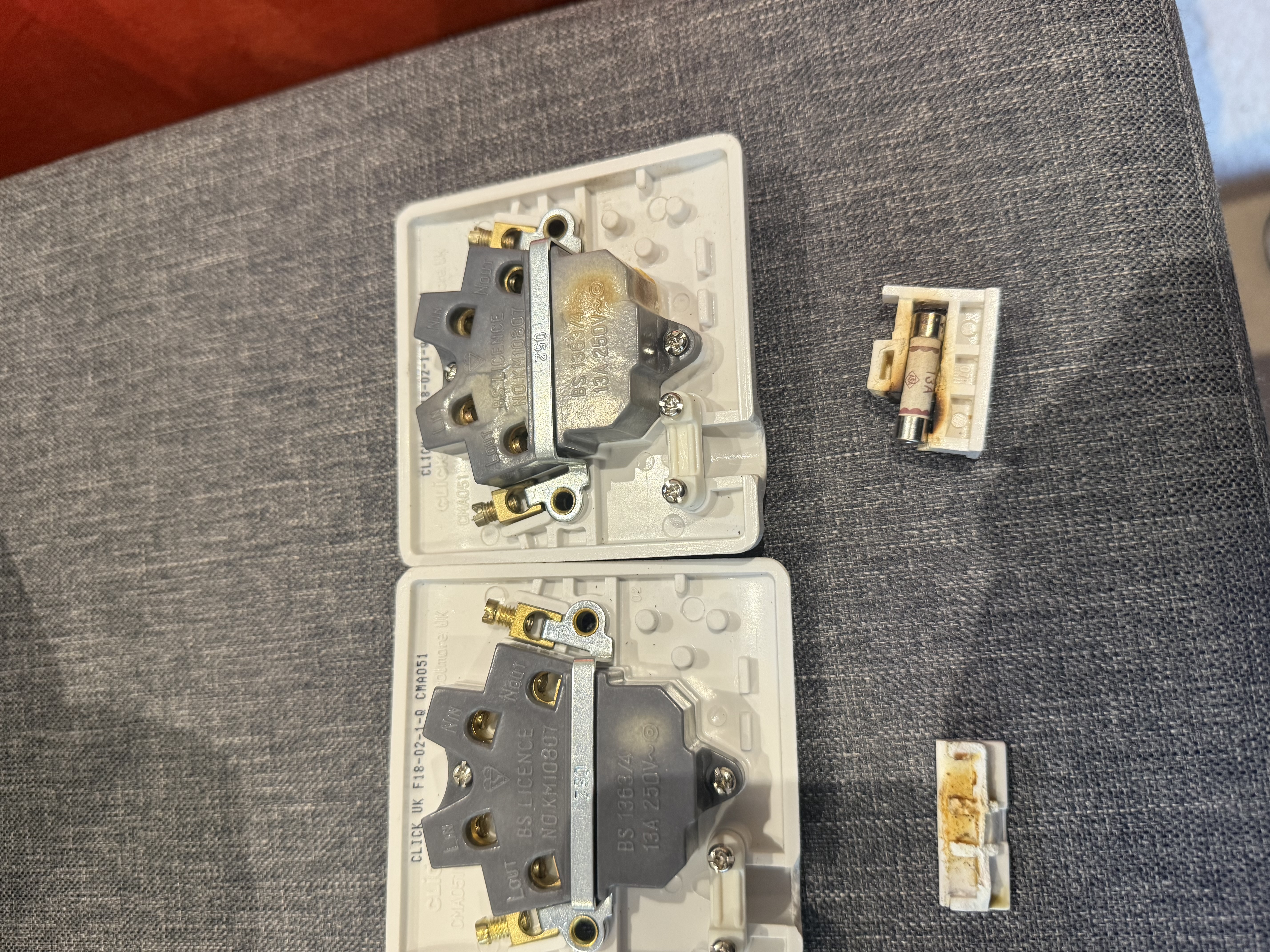
This type of fault is particularly significant because it may not produce the large fault current associated with a short circuit. Instead, components can progressively overheat over a prolonged period — in this case producing the visible damage to the fuse carrier, faceplate, conductors and housing that we found when the accessory was removed.
The repair
Simply replacing the damaged switchgear would not properly rectify the installation. The underlying circuit arrangement also needed correcting.
- Fault diagnosed: single 16 A circuit supplying two 3 kW immersion heaters — combined load of approximately 26 A.
- Heat-damaged fused connection units replaced, including the fuse carrier that had fused itself into the accessory.
- New dedicated 16 A circuit installed for each immersion heater, correctly rated for the individual load.
- New wiring installed where required.
- All terminations checked and tightened.
- Thermostats on both immersion heaters confirmed correct operation.
- Operating current of each heater verified using a clamp meter.
- Programmable timers installed — each heater configured to run approximately three hours twice daily.
- New circuits fully tested and certified.
- Work notified to Building Control as required.
- Thermal imaging inspection carried out the following day — no abnormal heating identified.
Timers — a practical improvement
We also installed programmable timers controlling each immersion heater, configured to run for approximately three hours twice each day rather than potentially remaining energised for prolonged periods. The thermostats remain the temperature control devices — the timers reduce unnecessary operating time and give the customer much greater control over when electricity is being used, which matters more now that immersion heating is a primary hot water source.
We came back the following day
For us, replacing the damaged components was not quite the end of the investigation. We returned the following day after the immersion heaters had been operating normally and carried out a thermal imaging inspection of the installation.
Thermal imaging is particularly useful following previous overheating because it allows us to look for abnormal temperature differences at terminals, protective devices, switchgear, cable connections, fused connection units and distribution equipment — without needing to dismantle anything.
The thermal inspection showed no abnormal heating, and we were satisfied that the repaired installation was operating correctly.
Changing how you use electricity — check the installation too
This job is a useful reminder that the way an electrical installation is used can change significantly over its lifetime. The customer had historically relied heavily on oil for heating and hot water. As fuel costs changed, electric immersion heating became more important. An electrical arrangement that had previously seen relatively limited use was suddenly being asked to supply a substantial load for prolonged periods — and that change in usage exposed an underlying design and connection problem.
It is becoming increasingly common for properties to change how they use electricity. Homes are adding or increasing their use of immersion heaters, electric heating, heat pumps, EV chargers, solar PV, battery storage, electric cooking and air conditioning. The electrical installation needs to be capable of supporting those changing loads safely.
Before significantly increasing electrical loads
- Check whether existing circuits were designed for the intended load
- Confirm cable sizes are appropriate for the current they will carry
- Verify protective devices are correctly rated
- Inspect connections and terminations for condition
- Consider thermal imaging where previous overheating is suspected
- Ensure new circuits are correctly certified and notified
At Omni3, we work across electrical installation, solar PV, battery storage, EV charging and energy systems — which allows us to look at the electrical installation as a complete system rather than simply replacing the component that has failed.
Sometimes a faulty switch is just a faulty switch. On this occasion, it was the first visible sign of a much bigger problem.
Related services
Electrical Services
Domestic and commercial electrical installation, fault finding and repair. NICEIC Approved Contractor.
EICR — Electrical Inspection
Periodic inspection and testing of electrical installations. Identifies deterioration, damage and non-compliant wiring.
Commercial Electrical
Planned electrical installation for commercial and industrial premises.
EV Charging
EV charge point installation — including supply assessment and consumer unit upgrades where required.
Solar PV
Solar panel installation for homes and businesses — including electrical design and certification.
All Case Studies
View all completed Omni3 projects across electrical, solar, EV, security and networks.
Electrical fault finding and installation — West Sussex
Omni3 investigates and repairs electrical faults for domestic and commercial customers across West Sussex and the South East. If something isn’t working correctly — or if you’re planning to increase your electrical loads — we can assess the installation properly before problems develop.